Recently, an awesome donor gave Redmond Python a bunch of PocketBeagle Beagle Boards. So as I started playing around with them to help folks learn about how to get started with them. This guide should get you programming your PocketBeagle within an hour with no additional hardware beyond a few cables and a MicroSD card. From there you can add hardware and explore to your heart’s content.
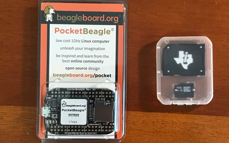
For anyone who isn’t familiar with PocketBeagles, they are “ultra-tiny-yet-complete open-source USB-key-fob computer[s].” and are a great board to get started learning hardware. You can read all about them on the BeagleBoard website but for now let’s try getting started with them ourselves!
Materials
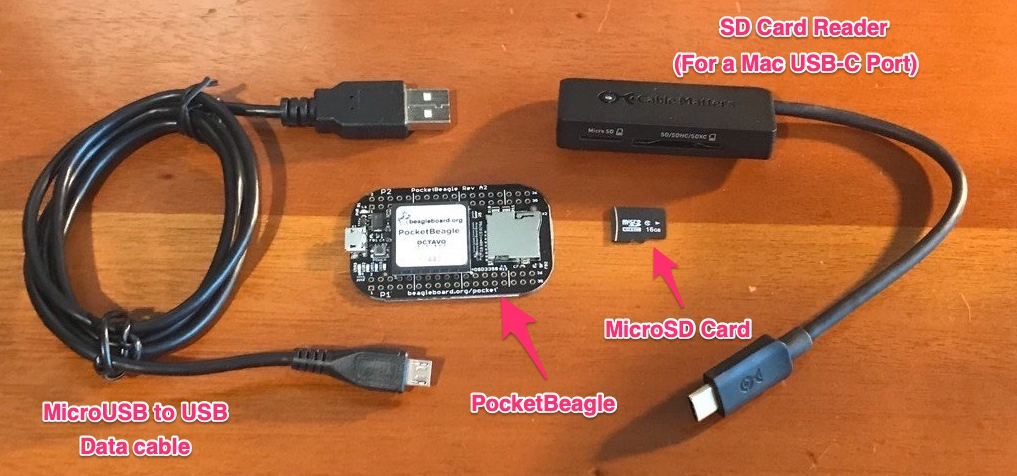
In order to get started I needed a few different materials (pictured below):
- The PocketBeagle
- A MicroSD card
- A MicroSD card reader for my computer
- A MicroUSB connector to your computer*
*be sure this is a data cable. Many cheap cellphone charger cables are charge-only cables and your computer will not be able to recognize the PocketBeagle using them. If you’ve ever transferred data with the cable before it should work.
With our materials all gathered we can get started setting up our PocketBeagle.
Downloading and Installing Our Firmware
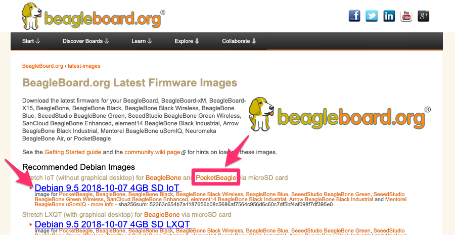
Our furst (heh, heh 🐶) step will be to download our operating system image. The latest firmware images specifically for BeagleBoards can be found at the BeagleBoard website.
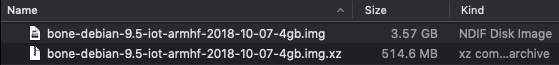
I downloaded the recommended image as of May 2019:
After we’ve downloaded this operating system image we can flash our MicroSD card with it.
As much as I’d like, it’s not as simple as copying the disk image to the card. In this step we deviate from the semi-confusion instructions inside the package a little to actually write the operating system to the MicroSD card.
You’ll need to use a program like Etcher, which you can download for free here, in order to flash your MicroSD drive.
After downloading and installing Etcher plug your MicroSD reader into your computer and insert the SD card. When your drive is recognized you can open up Etcher and should see something like this:
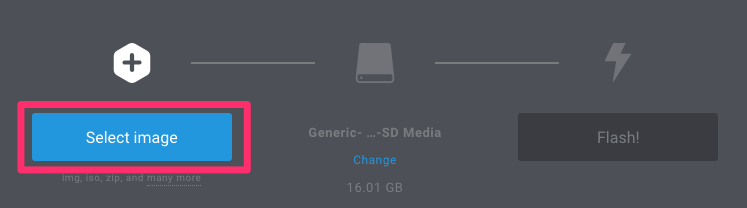
Click the “Select image” button and find the image you just downloaded. It should have either the .img extension or the .img.xy extension (Etcher supports using either a compressed or decompressed image).
After you select the image you may also need to select the MicroSD card from the drives on your machine. If you’ve already plugged the drive in before starting Etcher it might already show the drive selected and look like this:
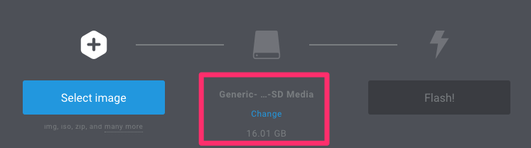
Once those two steps are done just press the “Flash!” button and wait for the process to finish. That process should take a few minutes but after it is done your MicroSD card should be ready for action.
After Etcher is done flashing your MicroSD card your operating system might prompt you to eject it. If it doesn’t, go ahead and remove the drive from the SD card reader.
Now with this card as our operating system image we can insert the card into the PockBeagle. Now the PocketBeagle was so compact I didn’t initially realize how to insert the MicroSD card at first. So here’s an example:
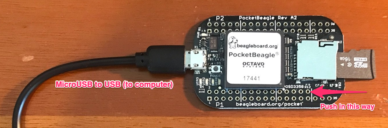
After the MicroSD card is inserted you can also connect the MicroUSB connector (shown above) and connect it to your computer.
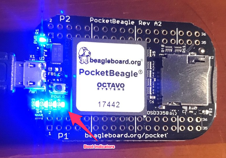
At this point the PocketBeagle should have one power light come on immediately as shown here:
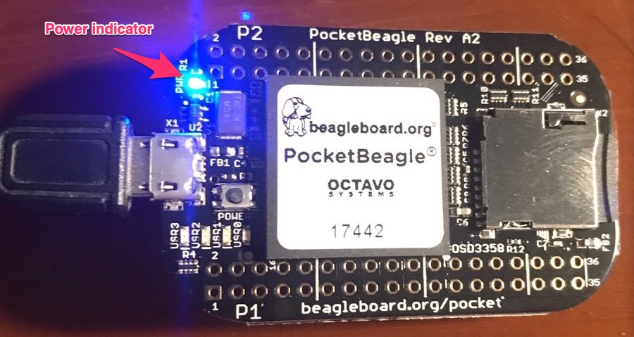
Within a few seconds after that, four other lights adjacent to one another turn on briefly and then a few may start flashing:
Connecting to the PocketBeagle
At this point your PocketBeagle is booting up and you should expect to see a new drive appear on your computer named BEAGLEBONE. Inside of that, you can open START.htm.
That file should load up a webpage with additional instructions on how to use the board. Internet Explorer probably wont work so open it in Chrome or Firefox.
Under Step 2 Enable a network connection, you should see a few options for IPs to load in order to connect to the board. Depending on your operating system you will navigate to 192.168.7.2 (for Windows) or 192.168.6.2 (for
Mac/Linux).
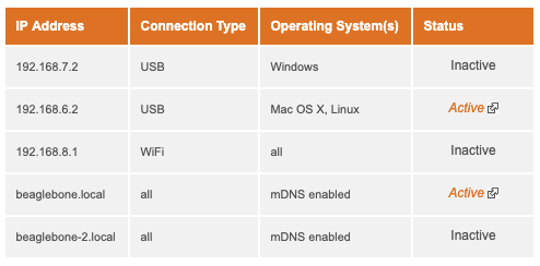
You can also try visiting beaglebone.local in your browser. After you’ve done this you should see something like the following:
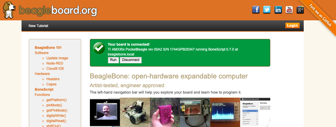
You can use this page to familiarize yourself with the details of working with the board. But for now, we’ll skip ahead to the fun stuff - making the pretty lights do what we want.
Programming Our Board
If you scroll down, the page you’re currently on has a handy tutorial on using JavaScript to manipulate the lights on the board:
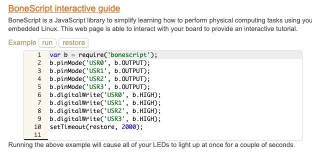
However, we want to program in Python. To do this, we can use the Cloud9 IDE that comes with the board. You can scroll down to the section of the page that mentions Cloud9 and click the Cloud9 title:
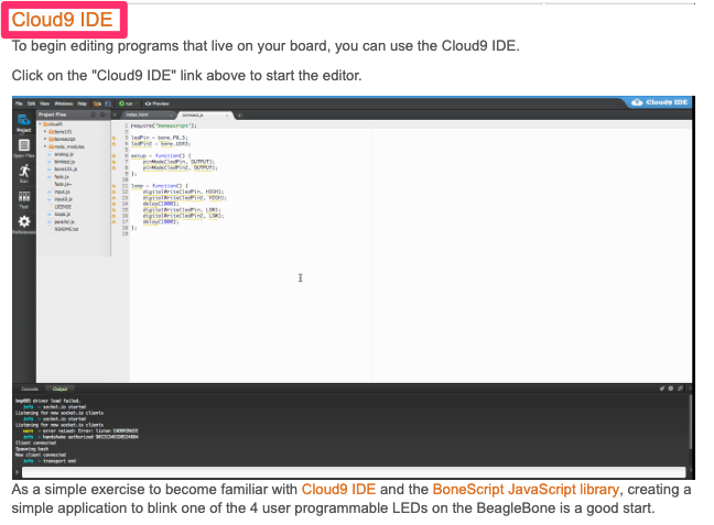
You can also visit beaglebone.local:3000 which should be where the Cloud9 tool is being served by the PockBeagle for you to use.
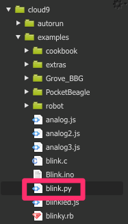
In this new window, there are a large number of examples you can use in the examples/ folder. Included in the examples is a blink.py file that you can click on and open up.
This file wont do anything for you right now because it sets up outputs that aren’t available on the PocketBeagle. By default, the file should look something like this:
import Adafruit_BBIO.GPIO as GPIO
import time

GPIO.setup("P9_14", GPIO.OUT)

while True:
    GPIO.output("P9_14", GPIO.HIGH)
    time.sleep(0.5)
    GPIO.output("P9_14", GPIO.LOW)
    time.sleep(0.5)
Now this file does some things for us, but it doesn’t set up the four USR0-USR3 lights as outputs for us to play with. Currently, they’re flashing in response to various internal board things like CPU usage. But, we can change this and set them up as outputs for our whims. Here’s how:
# Use the same library to manipulate the lights
import Adafruit_BBIO.GPIO as GPIO
import time

# Setup each of the USR lights as outputs
def setup():
    for i in ["USR0", "USR1", "USR2", "USR3"]:
        GPIO.setup(i, GPIO.OUT)

# Write a small function to manipulate the lights in a pattern
def vacillate():
    setup()
    while True:
        GPIO.output("USR3", GPIO.HIGH)
        time.sleep(0.5)
        GPIO.output("USR2", GPIO.HIGH)
        time.sleep(0.5)
        GPIO.output("USR1", GPIO.HIGH)
        time.sleep(0.5)
        GPIO.output("USR0", GPIO.HIGH)
        time.sleep(0.5)
        GPIO.output("USR0", GPIO.LOW)
        time.sleep(0.5)
        GPIO.output("USR1", GPIO.LOW)
        time.sleep(0.5)
        GPIO.output("USR2", GPIO.LOW)
        time.sleep(0.5)
But what does the code do?
But before we go on to the next step, what’s actually happening here? Well, first we write setup() with GPIO.setup(i, GPIO.OUT) to iterate through the USR light ids and set them up as outputs.
After that, we write the vacillate() function to turn the lights off and on using the GPIO.output() function. It takes the name of the output, in this case one of the USR0-USR3 lights and then we set the state using GPIO.HIGH or GPIO.LOW to turn it on or off respectively. The only other thing happening here is out use of the time library to slow the program down for half a second between each subsequent command.
Running Our New Program
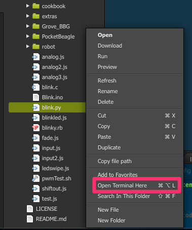
So let’s see this in action. Go ahead and replace all the old code in blink.py with the code above, then be sure to save the file. After that you can run this file from the terminal. You can open the terminal at the correct location by right-clicking blink.py and clicking Open Terminal Here as shown below:
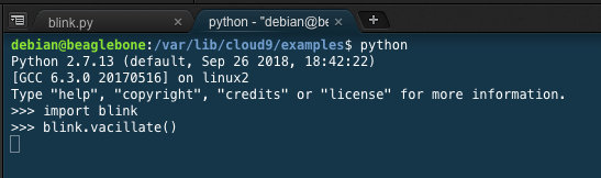
Then in this new terminal you can type in python and press enter to open the Python interpreter for the version of Python installed on the PocketBeagle.
Inside the interpreter you can then use the blink.py file you just wrote and call the vacillate() function in it too.
Here’s the code to type into the interpreter to do this, remember to press enter one more time at the end to run it:
import blink
blink.vacillate()
Here’s what it looks like when I do this:
And finally, with this code running you should see the lights on your board doing this:
If you’re seeing a less-blurry version of the video above, congrats! You’ve just programmed a BeagleBoard! If any of the previous steps gave you some issues, feel free to a leave a comment here so I can update the guide!
What next?
Now a challenge for you (with my own solution to it further down)! How would we write a function called pair_alternate() that would turn on USR3 and USR1 together and then alternate to turning on USR0 and USR2?
Give it a shot yourself and see if you can make it work! Or try something completely different! When you’re done, you can compare it to the function I wrote below. Just paste what I wrote into the bottom of the blink.py file and try calling the pair_alternate() function using the same steps as described for vacillate(). Just remember that if you already wrote your own pair_alternate() you might have to comment out your version first!
def pair_alternate():
    setup()
    while True:
        GPIO.output("USR3", GPIO.HIGH)
        GPIO.output("USR1", GPIO.HIGH)
        time.sleep(0.5)
        GPIO.output("USR3", GPIO.LOW)
        GPIO.output("USR1", GPIO.LOW)
        GPIO.output("USR2", GPIO.HIGH)
        GPIO.output("USR0", GPIO.HIGH)
        time.sleep(0.5)
        GPIO.output("USR3", GPIO.HIGH)
        GPIO.output("USR1", GPIO.HIGH)
        GPIO.output("USR2", GPIO.LOW)
        GPIO.output("USR0", GPIO.LOW)
        time.sleep(0.5)
Hopefully this has given you a fun introduction to working with PocketBeagle! If you’d like more hardware demos just let me know (and convince hardware companies to send me more cool stuff)!